CLAS Positioning with Septentrio mosaic-G5
This guide describes how to achieve centimetre-level CLAS PPP-RTK positioning using MRTKLIB with a Septentrio mosaic-G5 P3 receiver. We present two approaches: using the receiver's built-in RTK engine with VRS corrections generated by mrtk cssr2rtcm3, and using MRTKLIB's own PPP-RTK engine via mrtk run.
Overview
mosaic-G5 P3
The mosaic-G5 P3 is one of the few commercially available receivers that can directly track the QZSS L6 band and output raw L6D data. In this tutorial we used the mosaic-go G5 P3 evaluation kit (mosaic-go G5), which provides a convenient out-of-the-box setup for evaluating the mosaic-G5 P3 module.
Supported constellations and bands:
| Constellation | Bands |
|---|---|
| GPS | L1C/A, L1C, L1PY, L2C, L2P(Y), L5 |
| GLONASS | L1CA, L2CA, L2P, L3 CDMA |
| BeiDou | B1I, B1C, B2a, B2I, B2b, B3I |
| Galileo | E1, E5a, E5b, E6 |
| QZSS | L1C/A, L1C/B, L2C, L5, L6 |
Two Approaches: VRS vs. MRTKLIB Engine
VRS (mrtk cssr2rtcm3) | MRTKLIB Engine (mrtk run) | |
|---|---|---|
| How it works | Converts CLAS to RTCM3 and feeds corrections back to the receiver's built-in RTK engine | MRTKLIB's CLAS-dedicated PPP-RTK engine computes the position directly on the host |
| Host compute load | Lightweight — only format conversion runs on the host, so a minimal SBC (e.g. Raspberry Pi Zero) is sufficient | Heavier — full PPP-RTK pipeline runs on the host; a more capable SBC or laptop is recommended for real-time use |
| Where positioning happens | Inside the receiver (RTK engine consumes RTCM3) | On the host (MRTKLIB PPP-RTK engine consumes raw observations + L6D directly) |
Approach 1 — VRS (mrtk cssr2rtcm3)
In this approach, MRTKLIB converts CLAS corrections into standard RTCM3 MSM7 messages and feeds them back to the mosaic-G5, which then computes a VRS-based RTK position using its built-in engine.
mrtk relaybridges a single bidirectional serial port to the mosaic-G5: it forwards SBF tomrtk cssr2rtcm3over TCP, and its-b(relay-back) option feeds the RTCM3 it receives back into that same serial portmrtk cssr2rtcm3decodes L6D CSSR, computes OSR viaclas_ssr2osr(), encodes RTCM3 MSM7, and returns it tomrtk relayover the TCP loopback- The mosaic-G5 receives the RTCM3 corrections over the one serial port and computes a VRS-RTK position
mrtk relayalso outputs the positioning result (SBF/NMEA)
flowchart LR
    A["mosaic-G5 P3"] -- "Serial (SBF)" --> B["mrtk relay"]
    subgraph "Host (PC / SBC)"
    B -- "TCP/IP (SBF)" --> C["mrtk cssr2rtcm3"]
    C -- "TCP/IP (RTCM3)" --> B
    B -- "SBF" --> D@{ shape: stadium, label: "Output" }
    end
    B -- "Serial (RTCM3, relay-back)" --> A
Approach 2 — MRTKLIB Engine (mrtk run)
In this approach, MRTKLIB performs the PPP-RTK positioning directly. The mosaic-G5 serves only as an observation and correction source; all positioning computation happens on the host.
mrtk runreads the SBF stream from the mosaic-G5 (observations, L6D corrections, and broadcast NAV)- MRTKLIB decodes CLAS CSSR and computes the PPP-RTK position internally
- The positioning result is output directly from
mrtk run
flowchart LR
    A["mosaic-G5 P3"] -- "Serial (SBF)" --> B["mrtk run"]
    subgraph "Host (PC / SBC)"
    B -- "Positioning Result" --> C@{ shape: stadium, label: "Output" }
    end
Equipment
| Component | Description |
|---|---|
| Septentrio mosaic-go G5 P3 | Evaluation kit with mosaic-G5 P3 GNSS module |
| GNSS antenna | All-band antenna (L1/L2/L5/L6) |
| Host PC / SBC | Linux or macOS machine with MRTKLIB built (PC, laptop, or SBC such as Raspberry Pi) |
Where to buy the mosaic-go G5 P3 kit
- Global: Septentrio Online Shop
- Japan: CQ出版 オンラインショップ
Setting Up the Receiver
RxTools is a GNSS receiver control and analysis software suite by Septentrio. Configure the mosaic-G5 using RxTools (the mosaic-G5 module does not have a Web UI).
-
Download and install RxTools: Download the latest version of RxTools from the Septentrio website and install it on your computer.
-
Connect the receiver: Connect the mosaic-go G5 via USB. The board will be powered over USB and the LED will turn on.
-
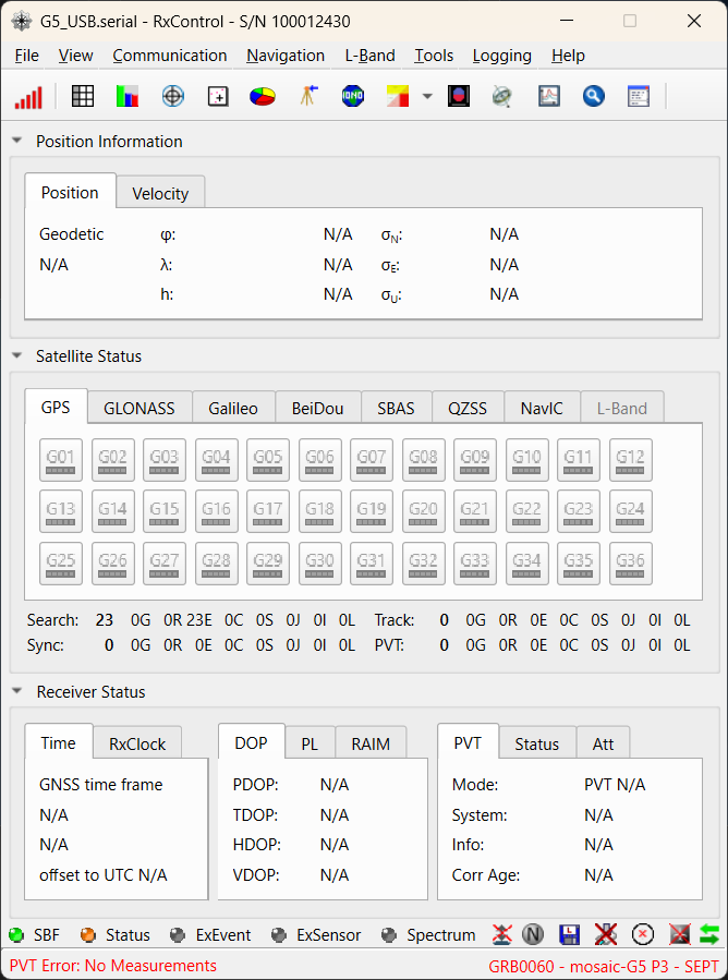
Launch RxControl: Open RxControl and configure the connection (first time only).
- Select
Serial Connection>Create New...
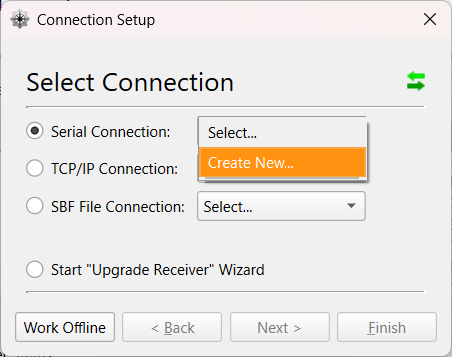
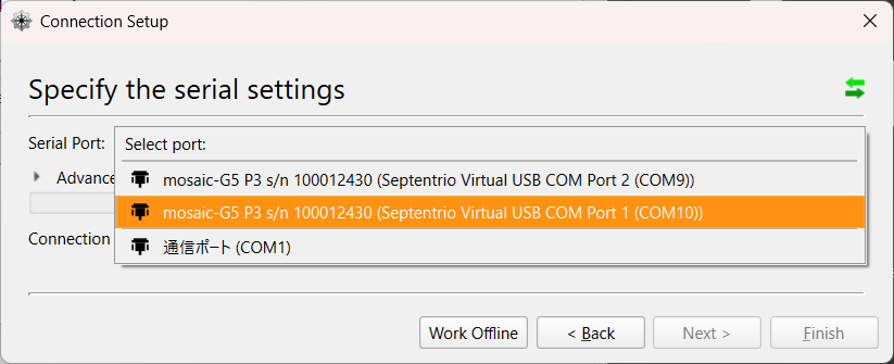
- Choose the USB COM port, set a
Connection Name, and clickFinish.
- RxControl will launch after the connection is established.
- Select
-
Set SBF output: Go to
Communication>Output Settings>SBF Outputand configureStream 1as follows:- Ports: the single bidirectional COM port (e.g.
COM1/USB1) — the same port you setRTCMv3input on in step 7, so one port carries SBF out and RTCM3 in. (On a multi-endpoint USB cable you may instead place SBF on a second endpoint and run two ports; the single-port form is simpler and is what the commands below assume.) - Off: unchecked
- Support: checked
- Interval:
1 sec(CLAS corrections update every 5 s and PVT can be paced at 1 Hz; 1 Hz is sufficient for static and most kinematic use cases. For high-rate dynamics, set100 msecinstead.)
Click
Apply, thenOKto close.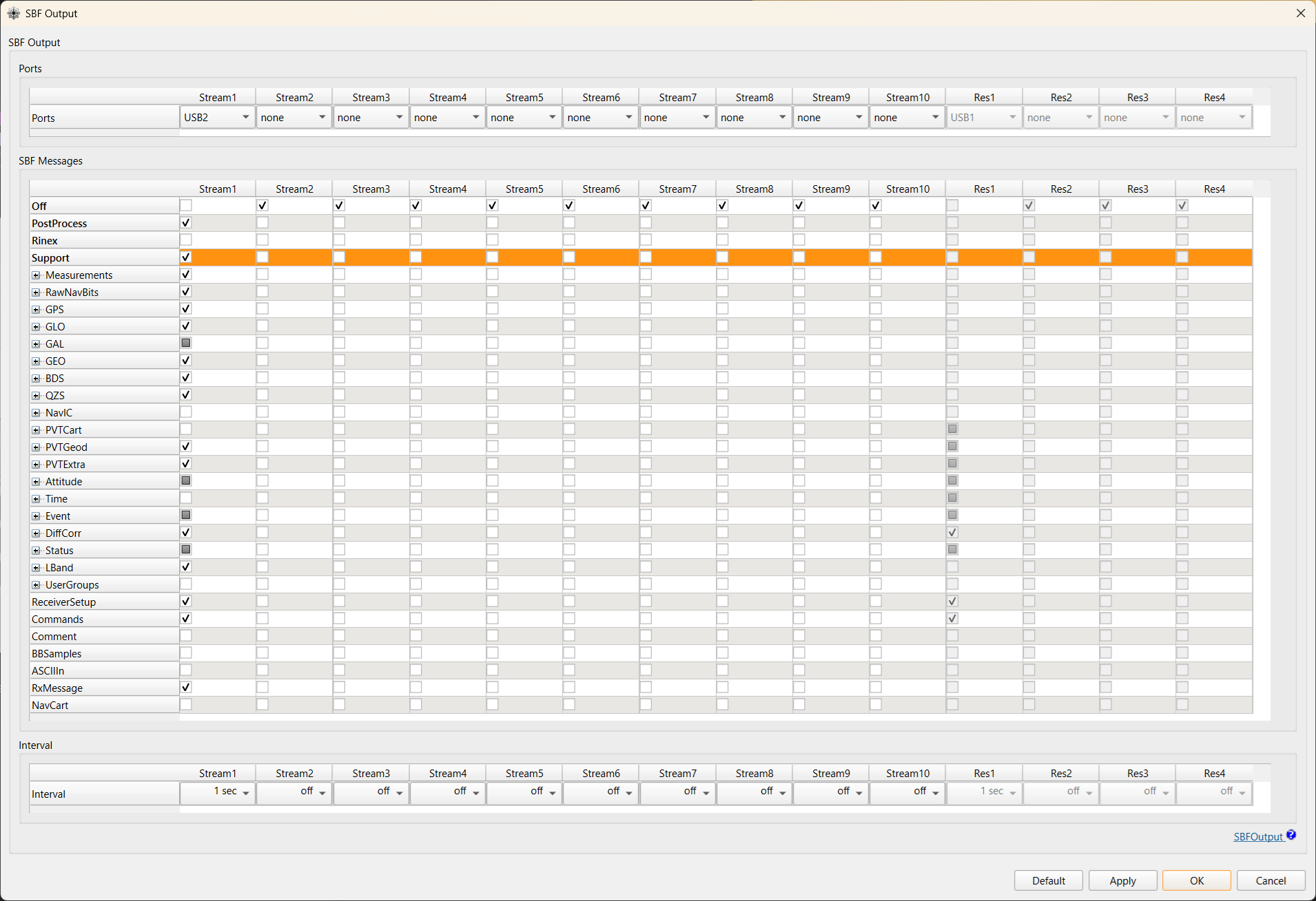
Required SBF blocks (reference)
Selecting
Supportenables a curated set of blocks that includes everything needed bymrtk cssr2rtcm3andmrtk run. The principal blocks consumed are listed below.SBF Block ID Purpose MeasEpoch 4027 Raw GNSS observations (required) QZSRawL6D 4270 QZSS L6D raw data (CLAS CSSR) GPSNav 4017 GPS broadcast ephemeris GALNav 4022 Galileo broadcast ephemeris QZSNav 4030 QZSS broadcast ephemeris GLONav 4004 GLONASS broadcast ephemeris (optional) BDSNav 4081 BeiDou broadcast ephemeris (optional) PVTGeodetic 4007 Receiver position (latched by mrtk cssr2rtcm3as the VRS reference)Note
Block IDs are listed for reference. Septentrio occasionally renumbers blocks across firmware revisions; consult the SBF Reference Guide that ships with your firmware version if you need exact IDs. Enabling
Supporton Stream 1 is the recommended way to ensure all required blocks are output regardless of firmware version. - Ports: the single bidirectional COM port (e.g.
-
Enable L6 tracking: Go to
Navigation>Advanced User Settings>Tracking, select theSignal Trackingtab, and enableQZSSL6. ClickApply, thenOKto close.L6 tracking is disabled by default
The mosaic-G5 does not track QZSS L6 signals out of the box. Without this step, the SBF stream will contain no
QZSRawL6Dblocks andcssr2rtcm3will receive no CLAS data.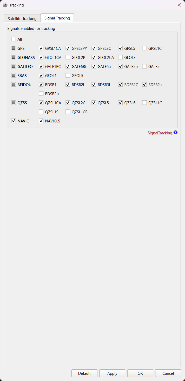
-
Set Positioning Mode: Go to
Navigation>Positioning Mode:- In the
PVT Modetab:- Enable RTK Float solutions: In the
PVT Modepanel, setRover modetoall(this allows the receiver to output Float solutions in addition to Fix). - Change Solution Selectivity: In the
Solution Selectivitypanel, setLeveltoLoose(this relaxes the strictness with which the PVT engine filters satellite signals and transitions between PVT modes).
- Enable RTK Float solutions: In the
- In the
PPP and Differential Correctionstab:- Change Max Age of Differential Corrections: In the
Max Age of Differential Correctionspanel, setMaximum age of RTK datato60.0s (aligned with the CLAS correction update interval).
- Change Max Age of Differential Corrections: In the
Click
Apply, thenOKto close. - In the
-
Configure the RTCM3 input port (Approach 1 / VRS only): On the single bidirectional setup this is the same COM port that outputs SBF (the one
mrtk relay -inconnects to, e.g.COM1/USB1). Set its Input Type explicitly toRTCMv3— output and input coexist on one port, as thegdioline below shows (RTCMv3in,SBF+NMEA+ASCIIDisplayout).Via RxControl GUI:
Communication>Input/Output Selection, choose the target port, setInput TypetoRTCMv3, clickApply.Via ASCII commands (USB1 terminal):
Verify with
gdio:autodoes not reliably detect RTCMv3The firmware reference states that
Input Type = autoauto-detects RTCMv3, but at least on firmware20250611bthis is not the case in practice — the receiver silently ignores incoming RTCM3 and stays in SPP mode forever, even whenmrtk cssr2rtcm3is producing valid corrections. Always set the InputType explicitly toRTCMv3for the port that receives corrections.Diagnostic symptom: PVT stays at mode = 1 (SPP / Stand-alone) indefinitely, with no transition to DGPS (mode = 2) / Float (mode = 5) / Fix (mode = 4), despite
mrtk cssr2rtcm3running and emitting RTCM3 bytes. At a clear-sky stationary point a 24 h SPP-only session can still cluster within ±15 cm — looks plausible at a glance, so check the PVT mode field inPVTGeodetic, not just the scatter plot.Also confirm that the COM port baud rate matches the host side (
mrtk relay -in serial://ttyACM0:115200⇒setComSettings, COM1, baud115200): -
Save configuration to the receiver: Go to
File>Copy Configurationand set:Field Value Source Current Target Boot Click
Apply, thenOKto close.Equivalent ASCII command:
Running — Approach 1: VRS
The VRS approach runs two processes simultaneously: mrtk relay to bridge the receiver's serial connection, and mrtk cssr2rtcm3 to convert CLAS corrections to RTCM3.
Both directions — SBF out of the receiver and RTCM3 back into it — travel over a single bidirectional serial port. mrtk relay serves the SBF stream on a TCP server port and uses its -b (relay-back) option to feed the RTCM3 it receives on that port back into the receiver's serial input. Only one COM port on the receiver is needed, so the same setup runs on a single-UART field SBC (e.g. a Raspberry Pi driving a mosaic-G5 P3 over a 3.3 V TTL header) and on a multi-endpoint USB connection (issue #117).
| Stream | Direction | Path |
|---|---|---|
| SBF | receiver → host | serial in → TCP server |
| RTCM3 (VRS) | host → receiver | TCP server → relay -b → serial in |
Note
Serial device names are platform-specific — /dev/tty.usbmodem… on macOS, /dev/ttyACM0 / /dev/ttyUSB0 / /dev/ttyS0 on Linux SBCs — and will differ on your system.
Step 1: Start mrtk relay
mrtk relay connects to the mosaic-G5 serial port, serves the SBF stream on a TCP server port, and relays the RTCM3 it receives on that port back to the receiver via the -b (relay-back) option.
# Terminal 1: bridge serial <-> TCP, relay RTCM3 back to the receiver
mrtk relay \
  -in serial://ttyACM0:115200 \
  -b 1 \
  -out tcpsvr://:9000 \
  -out file://mosaic-g5_%Y%m%d%h.sbf::S=1h
-in serial://ttyACM0:115200— read SBF from the mosaic-G5 serial port (COM1)-b 1— relay data received on output stream 1 (the TCP server below) back into the serial input. Streams are numbered from the input (stream 0), so-b 1is the first-out. This is what carries RTCM3 to the receiver over the same port.-out tcpsvr://:9000— output stream 1: serve SBF on TCP 9000 and accept RTCM3 back frommrtk cssr2rtcm3-out file://mosaic-g5_%Y%m%d%h.sbf::S=1h— output stream 2: log raw SBF, split hourly (optional, for post-analysis).::S=is the swap interval in hours: it is read as a plain number (sscanf("S=%lf")) and any trailing letters are ignored, so::S=1hand::S=1both mean 1 hour. Use a fraction for sub-hour splits (::S=0.5= 30 min); a suffix like::S=30mis not 30 minutes — it parses as 30 hours.
Keep the TCP server as the first -out
-b 1 points at the first -out. Put -out tcpsvr://… before -out file://… so the relay-back targets the TCP stream, not the log file.
Step 2: Start mrtk cssr2rtcm3
mrtk cssr2rtcm3 connects to the relay's TCP port, decodes CLAS CSSR from the SBF stream, and writes RTCM3 MSM7 corrections back to the same TCP port, where mrtk relay -b forwards them to the receiver.
# Terminal 2: CSSR -> RTCM3 conversion (RTCM3 returned over the TCP loopback)
mrtk cssr2rtcm3 \
  -k conf/cssr2rtcm3.toml \
  -in sbf://tcpcli://localhost:9000 \
  -out tcpcli://localhost:9000
-in sbf://tcpcli://localhost:9000— connect to the relay and read SBF (single-stream mode: L6D, NAV, and PVT are all extracted from the same SBF stream)-out tcpcli://localhost:9000— send RTCM3 MSM7 back to the relay's TCP server;mrtk relay -b 1relays it into the receiver's serial input
No second serial port is required: the RTCM3 return path is the relay's TCP loopback, not a separate COM port. Once the mosaic-G5 starts receiving valid RTCM3 (typically 1–2 minutes after corrections begin flowing — i.e. after CLAS convergence and broadcast-ephemeris collection), it performs VRS-RTK positioning internally. The result appears in the SBF output forwarded by mrtk relay; check the PVTGeodetic mode field for RTK Fixed.
Validated single-port operation (#117)
The single bidirectional-port topology above has been confirmed end-to-end on a mosaic-G5: with relay -b returning RTCM3 over one serial port, the receiver reaches and holds RTK Fixed. This is the recommended setup; it removes the second COM port the earlier two-endpoint configuration needed and so works on single-UART SBCs.
macOS: the relay's serial port is bidirectional here
With relay -b, the mrtk relay -in serial://… port now both reads SBF and writes RTCM3 back. On macOS, /dev/tty.* devices wait for the DCD (Data Carrier Detect) signal before completing the open, which can block writes silently — use /dev/cu.* for the relay's serial port on macOS. Linux /dev/ttyACM* / /dev/ttyUSB* are bidirectional as-is.
Monitoring with sbf_plot
sbf_plot.py connects to the relay's TCP port and plots the receiver's position and fix quality in real time.
# First time only: set up the Python virtual environment
# cd scripts && uv sync && source .venv/bin/activate && cd ..

# Terminal 3: Real-time position plot
python scripts/plotting/sbf_plot.py --port 9000
- Points are colored by fix quality: green = RTK Fix, orange = RTK Float, red = SPP
- The first received position is used as the reference origin (ENU in meters)
- To use an explicit reference:
--ref 35.3231,139.5221 - Fix rate and satellite count are shown in the title bar
Debug Trace
Add -d 3 to mrtk cssr2rtcm3 for detailed processing logs:
mrtk cssr2rtcm3 \
  -k conf/cssr2rtcm3.toml \
  -in sbf://tcpcli://localhost:9000 \
  -out tcpcli://localhost:9000 \
  -d 3
Running — Approach 2: MRTKLIB Engine
Instead of converting CLAS to RTCM3 and relying on the receiver's RTK engine, you can run MRTKLIB's own CLAS PPP-RTK engine directly.
Step 1: Start mrtk relay
Same as Approach 1:
Step 2: Start mrtk run
The MRTKLIB engine reads the SBF stream from the relay, automatically extracts L6D (CLAS) data from QZSRawL6D blocks, and performs PPP-RTK positioning. The NMEA solution is written to ./clas_rt.nmea by default.
To output the solution to a TCP server (e.g., for downstream applications):
Configuration
The default configuration conf/cssr2rtcm3.toml is suitable for most use cases:
# MRTKLIB Configuration (TOML v1.0.0)
# cssr2rtcm3: CSSR to RTCM3 MSM converter

[positioning]
mode = "ssr2osr"
elevation_mask = 0.0
satellite_ephemeris = "brdc+ssrapc"
systems = ["GPS", "Galileo", "QZSS"]

[positioning.corrections]
tidal_correction = "solid+otl-clasgrid+pole"
phase_windup = "on"
shapiro_delay = true
exclude_eclipse = true
receiver_antenna = false

[positioning.atmosphere]
ionosphere = "est-adaptive"
troposphere = "off"

[files]
# CLAS compact network grid definition (shared across all CLAS configs).
# Path is relative to the working directory where mrtk is invoked.
cssr_grid = "./tests/data/claslib/clas_grid.def"

# Signal code remapping: CLAS code → receiver tracking code.
# Key format: {G|R|E|J|C}{RINEX obs code}  (e.g. G2X = GPS L2X)
# Value: target RINEX obs code string       (e.g. "2W" = L2W)
#
# Uncomment and adjust for your receiver. Example for Septentrio mosaic-G5:
[signal_remap]
G2X = "2W" # GPS     L2C(M+L) → L2W  (needed: CLAS smode[1]=2X for most GPS sats)
#E1X = "1C" # Galileo E1(B+C)  → E1C
#E5X = "5Q" # Galileo E5a(I+Q) → E5aQ
J2X = "2L" # QZS     L2C(M+L) → L2L

# cssr2rtcm3-specific settings
[cssr2rtcm3]
# MSM message type: 4 (compact), 5 (+ Doppler), 7 (full resolution + Doppler)
msm_type = 7
# Constellations to include in RTCM3 MSM output (default: all CLAS systems)
# Recognised: GPS, Galileo, QZSS, GLONASS
systems = ["GPS", "Galileo", "QZSS"]
# SNR model for VRS pseudo-observations:
#   0 or omitted = elevation-dependent (25 + 20·sin(el) dB-Hz)
#   >0           = fixed value in dB-Hz (mosaic-CLAS uses 50)
snr_fixed = 50.0
# L6D satellite auto-selection: minimum elevation angle (degrees).
# cssr2rtcm3 watches all QZS satellites broadcasting L6D and selects the one
# with the highest elevation. When the selected satellite drops below this
# threshold, stops transmitting for >30 s, or another satellite reaches a
# clearly higher elevation, it fails over to the next best candidate.
# Default 10 degrees keeps GEO satellites (PRN >= 199) eligible.
l6d_elmin = 10.0
Key parameters:
| Parameter | Default | Description |
|---|---|---|
mode | ssr2osr | SSR-to-OSR conversion mode (required) |
systems | ["GPS", "Galileo", "QZSS"] | Constellations to include in RTCM3 output |
elevation_mask | 0.0 | Include all visible satellites |
ionosphere | est-adaptive | Adaptive ionospheric estimation |
cssr_grid | clas_grid.def | CLAS grid definition file |
l6d_elmin | 10.0 (deg) | Minimum elevation for QZS L6D satellite auto-selection. The selector picks the QZS satellite with the highest elevation above this threshold and fails over when the active satellite drops below it or stops broadcasting. |
Test Results
Test Configuration
The latest long-term static test was conducted under the following setup.
| Item | Value |
|---|---|
| Test site | Tokyo University of Marine Science and Technology, Etchujima Campus |
| Receiver | Septentrio mosaic-go G5 P3 evaluation kit |
| PVT output rate | 1 Hz (SBF Output Stream 1, Interval = sec1) |
| Solution Sensitivity | Loose |
| Max Age of RTK data | 60 s |
| MRTKLIB build | commit 3a8cc51 or later (eph_prev fix applied) |
| Session start | 2026-05-08 23:59 GPST |
| Session duration | 24 h continuous |
Block Diagram
flowchart LR
    A["mosaic-G5 P3"] -- "Serial/USB2" --> B["mrtk relay<br/>(SBF)"]
    subgraph "Host (PC / SBC)"
    B -- "SBF" --> C["mrtk cssr2rtcm3<br/>(RTCM Conversion)"]
    B --> E[("Log (SBF)")]
    end
C -- "Serial/USB1 (RTCM3)" --> A| Process | Role |
|---|---|
mrtk relay | Relay SBF stream to mrtk cssr2rtcm3 and log raw SBF |
mrtk cssr2rtcm3 | Convert CLAS CSSR to RTCM3 MSM7 in real time |
Long-term stability (24 h)
The first 24-hour continuous static test of the mosaic-G5 + mrtk cssr2rtcm3 chain produced the following result.
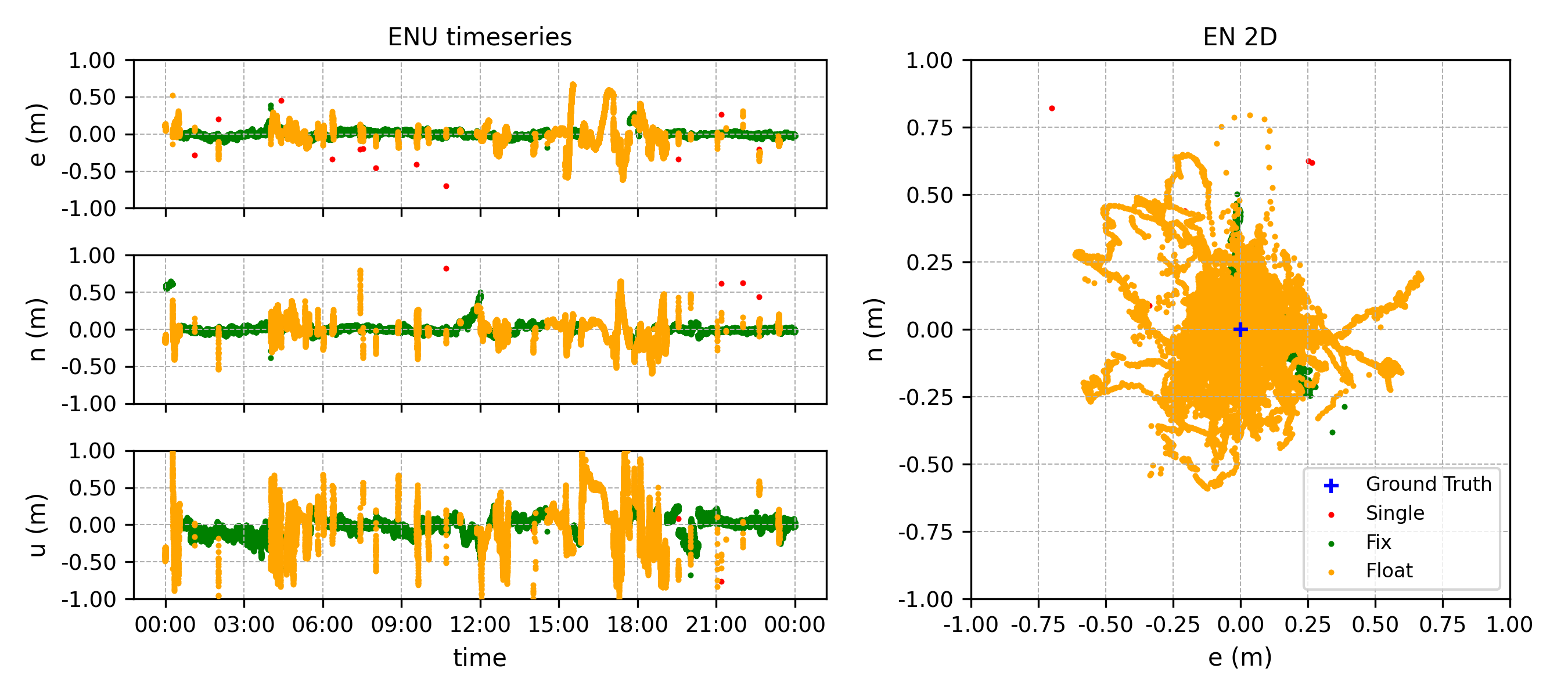
Solution mode breakdown (87,839 epochs, no data loss):
| Mode | Epochs | Share | Mean tracked sats |
|---|---|---|---|
| RTK Fix | 63,284 | 72.05% | 14.2 |
| RTK Float | 24,541 | 27.94% | 12.3 |
| DGPS | 0 | 0.00% | — |
| SPP (stand-alone) | 14 | 0.02% | — |
Hourly Fix rate (GPST hour-of-day):
| Hour | Fix % | Hour | Fix % | Hour | Fix % |
|---|---|---|---|---|---|
| 00 | 71.1 | 08 | 96.9 | 16 | 0.0 |
| 01 | 99.9 | 09 | 92.8 | 17 | 16.9 |
| 02 | 99.1 | 10 | 95.8 | 18 | 17.6 |
| 03 | 100.0 | 11 | 95.5 | 19 | 85.2 |
| 04 | 23.2 | 12 | 27.9 | 20 | 99.6 |
| 05 | 45.8 | 13 | 90.4 | 21 | 99.6 |
| 06 | 92.8 | 14 | 56.6 | 22 | 99.0 |
| 07 | 98.7 | 15 | 28.0 | 23 | 96.1 |
Highlights:
- 24 h continuous operation with no crashes and no output stalls, confirming long-running daemon stability after the recent
actualdistfixes (d028b0c,7fb497f) and theeph_prevcorrection-continuity fix (3a8cc51). - DGPS dips eliminated: the 10-minute periodic DGPS dip seen in earlier builds did not reappear (DGPS reached 0 epochs over 24 h).
- 16 of 24 hours achieved ≥ 90 % Fix rate (8 hours at ≥ 99 %).
- Two windows account for almost all of the Float share: h ≈ 04–05 GPST (~2 h, 23–46 % Fix) and h ≈ 14–18 GPST (~5 h, 0–57 % Fix; one full hour at 0 % Fix). In both windows the tracked-satellite count (ns ≈ 12) and DGPS correction age (~2 s) were healthy, so the cause is neither observation starvation nor a correction-link outage — investigation is ongoing (see Known Issues and #98).
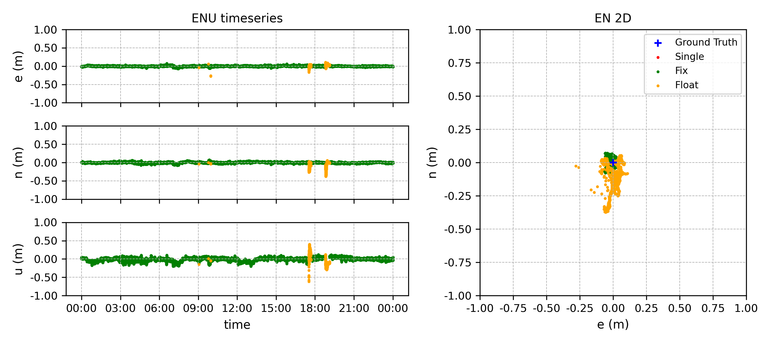
Reference comparison: mosaic-CLAS
For context, a 24-hour static run of a Septentrio mosaic-CLAS receiver at a different location in the Kantō region on the same day produced the following result.
| Stream | Fix | Float | DGPS | SPP |
|---|---|---|---|---|
mosaic-G5 + mrtk cssr2rtcm3 (this guide) | 72.05 % | 27.94 % | 0.00 % | 0.02 % |
mosaic-CLAS (reference) | 97.96 % | 2.02 % | 0.01 % | 0.00 % |
The mosaic-CLAS reference is at a different site and uses different hardware, so this is not a like-for-like comparison; nevertheless it indicates that there is still meaningful headroom in the cssr2rtcm3 → external RTK engine path relative to a receiver that consumes CLAS L6D natively. See #98 for the investigation tracking this gap.
Known Issues
Fix-rate gap vs. mosaic-CLAS reference — #98
In the 24-hour static test summarised above, the cssr2rtcm3 → mosaic-G5 chain achieved a 72 % Fix rate, versus 98 % on a mosaic-CLAS reference at a different Kantō site on the same day — a remaining headroom of roughly 20 %. Two windows (h ≈ 04–05 and h ≈ 14–18 GPST) showed sustained drops in Fix rate while the tracked-satellite count (≈ 12) and the DGPS correction age (≈ 2 s) remained healthy. The corrections were arriving on time and enough satellites were tracked, yet integer ambiguities did not consolidate to Fix in those windows.
Possible causes under investigation include cycle-slip cascades on specific PRNs, ionospheric activity around dawn / late afternoon, the elevation profile of the active L6D satellite, and CLAS network-region transitions. Tracking issue: #98.
Vertical-component dispersion (~30 s sawtooth) — #97
When solutions are plotted, the vertical (Up) component shows a roughly 30-second sawtooth pattern of a few centimetres peak-to-peak that is not present in reference implementations processing the same data. Horizontal accuracy is unaffected.
The cause is cssr2rtcm3's extrapolation of CLAS Compact SSR orbit/clock corrections between snapshots: rate terms are currently held at zero, so each ~30 s SSR update introduces a small step in the corrected satellite position/clock that propagates into the vertical component. Estimating the rate by numerical differentiation between consecutive snapshots is being investigated as a remediation.
This is a property of the correction extrapolation logic, not a receiver-specific issue; any RTK engine consuming this RTCM3 stream is expected to show the same pattern.